Hoses production
Everything you need to know about the production of original PARSCH hoses.
Weighing of raw materials for the rubber Manchon
Each compound for the inner lining of a hose consists of about 25 different raw materials. The majority consists of rubber, fillers and small additives of chemicals and accelerators. By the addition of carbon black, the synthetic rubber is dyed black.
There are 6 different basic qualities for the inner lining:
- SBR rubber
- EPDM rubber
- Neoprene rubber (also called CR rubber) for oil and gasoline resistance, as well as high abrasion
- NBR rubber for oil resistance, gasoline resistance and conductivity
- NBR/PVC
- Chlorobutyl
These mixtures are weighed according to given recipes developed at PARSCH. Due to constantly expanding requirements (e.g., increased ozone values or higher mechanical stress), we are continuously refining the recipes.
In order for the worker to be able to produce the correct recipe, the type and weight of the raw material is given to him on a display via a PC. Each individual raw material container is labeled. A red LED lights up to indicate from which container a chemical must be removed. During the weighing of the raw materials, the operator must press two confirmation keys with both hands once the target weight has been reached, before the next raw material is shown on the display.
After the recipe has been weighed, the containers with the individual raw materials and a product sheet are conveyed to the kneader by means of an elevator and a conveyor belt.
Kneader
The kneader (a mixing machine) performs the task of mixing the raw materials that have been brought to it after weighing. Below the kneader platform, a roller mill ensures that the kneaded mixtures are made homogeneous.
The sequence in which the raw materials are to be poured into the kneader is specified on a display via a PC. The input of the raw materials takes place in 2 – 4 stages.
The kneader flap opens automatically at each stage enabling the corresponding raw materials to be filled in. There are 2 rollers in the kneader, which move contrary to each other.
Subsequently, a flap opens at the bottom and the mixture falls onto the roller mill. This is where two water-cooled rollers rotate against one another, cooling the finished mixtures and rolling them out into a mixture sheet.
The operator cuts the rolled-out compound into sections (GU profiles) on the water-cooled rolls and stores them on respective transport carts until the rubber is further processed in the extruder.
Rubber hose extrusion
The chamber above the extruder is loaded with mixture pellets (GU profiles) by a worker. These are then automatically inserted into the extruder via a light barrier.
An extruder screw heats the rubber to approx. 80 degrees Celsius. This builds up pressure and allows the rubber to be pressed through a strainer screen.
➝ Pressures of up to 400 bar occur here.
The extruder head consists of a die and an iron mandrel. The distance or air gap – mandrel/matrices – determines the thickness of the tube.
In front of the extruder head is a screen that retains impurities (strainer screen).
In addition, a thin tube through which powder (talcum powder) is blown into the inside of the rubber hose by means of air can also be found here. The talcum powder prevents the rubber from sticking from the inside.
The rubber is molded into a hose like chewing gum. A flat-width measuring device monitors the dimensional accuracy of the extruded hose. After extrusion, the hose is passed into the heating channel so that the chemicals react, and the rubber hose vulcanizes.
After the hot air channel, a solid adhesive is applied to the black inner hose with an extruder.
Afterwards, the rubber passes through a water bath for cooling down to room temperature.
Next, the hose is led further through a powder machine and coated from the outside with a release agent so that the individual rubber layers do not stick together during intermediate storage in the transportation container.
This release agent is subsequently melted away in the following production steps in order to obtain optimum product properties.
Fabric manufacturing
The hose fabric consists of polyester, nylon, or polypropylene fibers.
It is manufactured in a circular weaving process and consists of weft threads (running crosswise) and warp threads (running lengthwise). The weft thread provides the pressure load on the hose. The warp thread protects it from damage (abrasion) and therefore must be designed to be sufficiently strong to meet the requirements.
Twisting
Multiple single yarns, of 1100 dtex with 70 N breaking strength, are twisted together on twisting machines (warp and weft twisting machines) to form one yarn.
(For example: 5 x 70 N = 350 N/thread).
On the warp twisting machine, warp threads are twisted 2 to 5 times, out of yarn bobbins delivered to us, onto the so-called warp bobbins (small bobbins for loading the yarn creels).
On the weft twisting machine the weft yarns, which can withstand the pressure in the tube, are twisted. (3 to 18-ply => 3-18 individual threads).
The 1100 dtex threads consist of about 192 thin filaments.
Benefits of twisted yarn:
➝ improved abrasion resistance
➝ higher tensile strength of the single thread
➝ fewer single threads in the weaving process.
From the twisting mill, the finished packages proceed to the weaving mill.
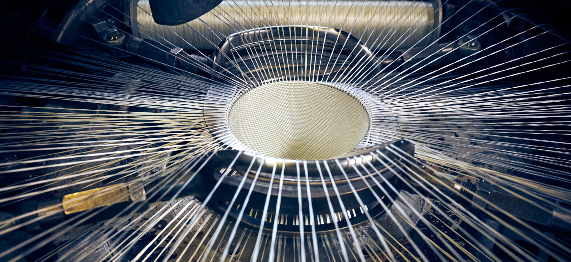
Weaving
In the weaving mill, the tubular fabric for our hoses is manufactured in a circular weaving process.
Depending on the diameter to be woven, there are up to one thousand warp bobbins per machine on a warp yarn creel. The yarn is fed directly to the loom, onto the weaving platform. From there, the twisted yarn is passed on to the weaving form via yarn brakes, ensuring that the same yarn tension is achieved at the weaving head.
The weft bobbins, on which the weft thread has been twisted on, rotate around the weaving form, whereby the weft thread is woven into fabric together with the warp thread (threads running in the longitudinal direction).
The inner rubber is inserted into the loom from above. The machine movement loosely weaves warp and weft threads around the rubber.
Vulcanization
➝ Connection between the inner rubber and the fabric hose to form a finished hose (adhesion).
In continuous vulcanization, the hoses are first inflated with air from the inside so that the inner rubber is pressed against the fabric from the inside.
Then, the hose is pulled through a hot-air vulcanization channel. Here, at a high temperature, the adhesive is brought to vulcanization.
Afterwards, the Manchon and the fabric are permanently welded together by simultaneous pressing (vulcanization).
As a result, the pressure-bearing fabric is sealed from the inside by the Manchon. The substance, e.g., water, which is passed through the hose, can now no longer escape. Additionally, the hose can be coated/dyed on the outside with a color and/or coating. On the outside, the fabric can be sealed by means of an additional PU melt.
Advantage:
Due to a smooth, closed surface, there is a higher abrasion protection and a better cleaning possibility of the hose. Furthermore, the PU coating prevents water from being absorbed by the fabric.
Optionally, hoses with a rubber outer cover can also be manufactured in this process (co-extrusion process).
As the hose passes through a hole control device with automatic display.
The hose is reeled endlessly onto reels and moves from there via the measuring table onto the correctly sized transport or storage containers. On the measuring table, the endless hose is cut to predefined lengths and is simultaneously checked for external defects. In parallel, the hose is often already labeled and coiled according to the respective specifications. From the measuring table on the endless line, the hose lengths – which are not stored – are sent for binding. Different couplings are fitted to the hoses, for example couplings made of light metal, brass, stainless steel, etc., and which comply with the various systems and respective standards.
Finally, the finished hoses are taken to the shipping department to be packed for transport to the respective customer. The hoses are then shipped by truck, container, rail, ship, or air.
Vulcanization table
Inner and outer rubberized hoses as well as special hoses such as cable protection hoses are manufactured at the vulcanizing table. Here, the hoses are vulcanized with steam. In addition, hose pressure tests with water are also carried out at the vulcanizing table.
Laboratory
In the laboratory, all required tests are carried out on finished hoses, semi-finished products such as rubber compounds and Manchon or on supplied raw materials (yarn) according to the specifications of various standards (DIN 14811:2008-1 and other domestic and foreign specifications).
Since PARSCH is certified according to the internationally valid quality standard DIN EN ISO 9001:2015, the customer has the certainty that the required tests are carried out and the results obtained are evaluated and recorded accordingly.
Including:
➝ Pressure tests: The burst pressure of the hose according to DIN 14811:2008, 60 bar. The nominal burst pressure of a first sample of a hose must be approx. 10 % above the required burst pressure.
➝ Rubber (rheometer): Rubber samples are vulcanized on the rheometer and the shape of a curve is recorded. Sample templates are available with which the curves from the sample vulcanization can be compared. In this way, immediate action can be taken in the event of deviations.
➝ Flame test: The temperature of the flame is approx. 800 degrees C. It is applied to the hose from below for 10 seconds at a water pressure of 5 bar to test whether the hose can withstand the temperatures.
➝ Abrasion test: According to DIN 14811:2008-01, hoses are scrubbed with 80 – 600 rotations. According to the French standard, rubbing is performed in the longitudinal direction and according to the British standard, rubbing is performed at an angle, 45 degrees. The abrasion test provides information about the abrasion resistance of the hose.
Assembly
Binding of couplings
– Wire
– Sleeves
– Other types of binding